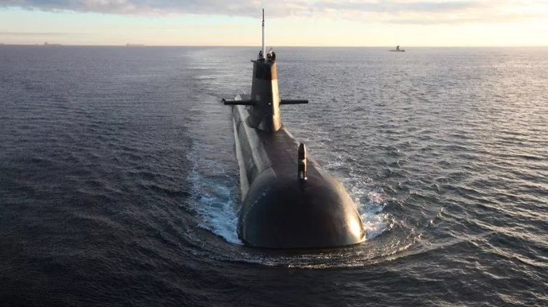
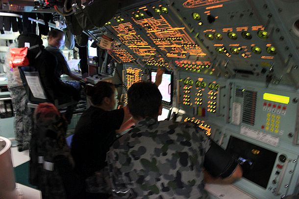
The complex electrical power systems on board the Australian Collins Class Submarine fleet have to power all the equipment in the submarines, such as the main motors, vessel controls, lighting, Sonar, combat system, weapon systems, compressed air, and many more.
The submarines have had numerous upgrades over many years, with equipment and systems being replaced, in some cases several times during the life of each submarine. The upgraded equipment often loads the electrical system differently from the original equipment. While allowance is generally made in the electrical power wiring to support extra equipment loads, there will naturally be a limit to how much extra load can be placed on each circuit before it has the potential to become unstable.
Hence, with submarine maintenance upgrades still planned over the coming years, it is becoming critical to know exactly what demands exist on the power systems, and how the loads behave during submarine missions, so that future upgrades can be planned with confidence.
Esis was engaged by ASC (Australian Submarine Corporation) in 2017 to develop and supply an electrical power data logging system as a trial to be installed on one submarine, with a view to further developing it for deployment in the rest of the fleet after the initial trial.
Project Requirements
The system must monitor and record power data from 22x 3-phase AC circuits, and 8x low voltage DC circuits, on board the submarine. The system must have minimal impact on crew workload, working autonomously without any intervention, for several months at a time.
Two data logging systems are required to be installed at different positions within the submarine. One of the systems needs to monitor 16x 3-phase AC circuits, plus 4x DC circuits. The other system needed to monitor 6x 3-phase AC circuits plus 4x DC circuits.
Different circuits are rated at different amperages and voltages, so various different sized current sensors are required.
Parameters to be measured included voltage, current, kVA/kW, power factor (apparent and displacement), and AC frequency. These are required to be sampled at intervals of a few minutes or better, with calculations to obtain average and maximum per day and per mission.
Other requirements of the system were that it must physically fit within the available space on the submarine, which is extremely limited; and wiring up all the voltage cables and current transformers should be relatively easy to do. It also needs to be reasonably easy and quick for engineering staff to download and analyse the recorded data when the submarine returns to its home location.
Data Logging Solution
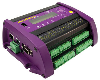
The data logging solution from Esis consisted of 2x Datataker DT80 Series 4 data loggers, along with 3x Dent PowerScout 24 Modbus AC power meters. A variety of AC and DC current sensors were also supplied, matching the requirements of each circuit to be monitored.
Two of the PowerScout boards were integrated into a single enclosure by Esis to fit in the limited space available.
The Datataker loggers were upgraded by Esis to have 2GB internal flash memory, instead of the default 128MB. Esis then developed a complex Datataker script to meet the requirements. Due to the large number of data points being calculated and recorded, the Datataker script had to be written and tweaked carefully to avoid going over the calculation memory capacity and storage capacity of the Datataker.
The script handled the following tasks:
- Connect to the PowerScout units via Modbus/RTU, and interrogate them for all the required AC measurements at 5 second intervals;
- Apply scaling factors to the 16-bit Modbus data, to convert them to real world units;
- Maintain running totals and calculate the average and maximum of most measurements over time, so they can be recorded at a slower rate to conserve memory;
- Measure the DC voltages and currents using the Datataker’s analog inputs;
- Calculate the required DC parameters such as DC kilowatts, and their average/maximum values, and maintain average/maximum of these measurements over time as well;
- Record the required measurements/averages/maximum values at the required intervals of several minutes / daily max / mission max;
- Correctly handle situations such as power outages, loss of communications, etc;
- Calculate and display the remaining memory in days;
- Provide front panel menu options to start and stop logging, clear the accumulated data, and spot check the current measurements;
- Store all recorded data safely and make it quick easy to unload the large volumes of data at the end of a data logging session.
Integration and Commissioning

The programming, integration and testing of the equipment was initially carried out at Esis’ premises. Esis engineers also developed documentation for installation and operation of the system. Once the system was ready, it was delivered to ASC, who then carried out evaluation and testing in their workshop before proceeding to install it in the submarine.
The submarine installation went smoothly, with the equipment neatly fitting into the required space, and the wiring was correctly completed by ASC’s highly competent electricians and engineers.
An Esis engineer was then engaged to attend the ASC West site for final testing and commissioning of the system. During the final test, the data logging system worked exactly as designed, and all measurements tested out correctly compared with an independent handheld meter. Data download was tested and worked within the required time limits. The recorded data was then analysed using the DPlot graphing software provided with the Datatakers. Training and documentation was also given to the ASC engineers for how to operate the system and unload data.
Customer Comments
“ESIS worked diligently to provide us with a product that met our requirements.
The product that we received has to date, operated as intended and future designs are intended using the current system as a baseline.
Chris was always responsive to our communications which requested his expertise to explore the capabilities that were available to us.”
– Mark Shawcross, Senior Electrical Engineer, ASC


